In the bustling world of vending machines, where convenience meets technology, the inner workings may seem like a mystery to many. However, at the heart of these machines lies a network of connectors that facilitate the communication between various components. Understanding the pinouts of these connectors is crucial for maintenance, troubleshooting, and even customization. Let’s delve into the commonly found connector pinouts in vending machines to shed some light on this essential aspect of their functionality.
Many of the peripheral inside the vending machine uses connectors that has become a standard across the vending industry.
- coin/notes acceptors,
- payment terminal,
- printer,
- telemetry system
Standardisation of communication connector plays a pivotal role in the functionality and maintenance of vending machines. By comprehending the configuration and purpose of these connectors, operators and technicians can ensure smooth operation, efficient servicing, and seamless integration of new technologies into vending machine systems. As vending machines continue to evolve with advancements in technology and consumer preferences, familiarity with connector pinouts will remain indispensable in the vending industry.
This page summaries standard connectors pinout that are very commonly found in the Vending Machines industry.
MDB (Multi-Drop Bus)
The MDB connector is perhaps the most ubiquitous in vending machines, serving as the primary interface for communication between the machine’s controller and peripheral devices such as bill validators, coin mechanisms, and cashless payment systems. It typically consists of multiple pins carrying signals for data transfer, power, and ground. The pinout configuration adheres to a standardized protocol established by the vending industry to ensure compatibility between different manufacturers’ components.
Common pins found in an MDB connector include:
- Power (+12VDC and GND): Provides power supply for peripheral devices.
- Data lines (Tx and Rx): Transmit and receive data between the controller and peripherals.
- Control signals (e.g., Enable, Reset): Facilitate device control and synchronization.
- Serial Interface (e.g., MDB, BDV): Implements communication protocols for specific peripherals.
Understanding the MDB pinout is essential for integrating new devices, diagnosing communication issues, and ensuring proper functionality of vending machine components.
Click here for MDB cable connection pin out.
VCCS
This is a standard interface used by Coca-Cola in Japan and other Asian Pacific Rim countries. It’s a serial interface that supports coin, cashless, and bill note payment systems. It uses a single connector for power and two-way communication signals. The protocol is primarily focused on specific coin references.
Click here for VCCS cable connection pin out.
Coin Acceptor
Coin acceptors, also known as coin validators or coin mechanisms, are devices used in vending machines, arcade games, and various other coin-operated devices to accept and validate coins. The standard connector pinout for a coin acceptor can vary depending on the manufacturer and model.
Here’s a typical pinout for a coin acceptor connector:
- Coin Signal Output: This pin provides a signal indicating that a coin has been accepted and validated. It usually sends a pulse or some form of signal to the machine’s control system to indicate the acceptance of a coin.
- Power Supply (+12V or +24V): Most coin acceptors require a power supply to operate. This pin provides the necessary voltage (usually +12V or +24V) to power the internal circuitry of the coin acceptor.
- Ground (GND): This pin provides the ground connection for the coin acceptor. It completes the electrical circuit and is necessary for the proper functioning of the device.
- Coin Reject Signal Output (Optional): Some coin acceptors may have an additional pin for signaling when a coin has been rejected or not accepted. This can be useful for troubleshooting or for implementing features such as coin return mechanisms.
- Serial Communication (Optional): In more advanced coin acceptors, especially those used in modern vending machines, there may be pins dedicated to serial communication. These pins allow the coin acceptor to communicate with the machine’s control system, providing detailed information about the coins accepted and enabling advanced features such as auditing and remote monitoring.
- Configuration/Programming Pins (Optional): Certain coin acceptors may have pins dedicated to configuration or programming purposes. These pins allow the adjustment of settings such as coin acceptance criteria, coin denominations, or pulse output characteristics.
It’s important to note that this pinout is a generalization, and the actual pin configuration may vary depending on the specific make and model of the coin acceptor. Additionally, always refer to the manufacturer’s documentation for the precise pinout and connection details for your particular coin acceptor model.
Click here for the typical cable connector wiring pin out of the most popular coin acceptor.
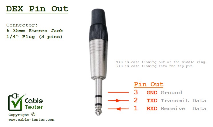
DEX (Data Exchange)
The DEX connector serves as a standardized interface for connecting vending machines to external systems such as route management software, inventory tracking systems, and telemetry devices. It enables the exchange of data related to sales, inventory levels, and machine status, allowing operators to monitor and manage their vending fleets remotely.
Key pins in a DEX connector may include:
- Serial Data Lines: Transmit sales and inventory data in a standardized format (e.g., NAMA or VMC).
- Power and Ground: Provide necessary power supply for DEX communication.
- Control Signals: Enable/disable DEX communication and initiate data transfers.
Operators rely on the DEX pinout to integrate vending machines into their backend systems, streamline operations, and gather valuable insights into sales performance and inventory management.
Click here for DEX connector pin out.
CCTalk (Coin Communication Protocol)