Introduction to Coin Acceptor Connector
A coin acceptor is one of the oldest forms of automatic payment collecting mechanism used in vending machines. The signaling interface is typically a simple pulse. It is triggered by the npn transistor from the coin acceptor. There is no industrial standard set on this pulse interface. However, due to their wide use in the industry, certain wiring and connector connections have become more common than others. Competition copying the same interface. And eventually, a pretty common pin-out standard emerged for the coin acceptor.
Please note that not all coin acceptor has the same connector type or the same pinout. It is recommended to always refer to your coin acceptor’s product document for accurate information.
Coin Acceptor Connector details
Socket on PCB board
JST XH Series (2.5mm pitch), 4 ways
- Top Entry type (buy part number: B4B-XH-AM)
- Side Entry type (buy part number: S4B-XH-A-1, S4B-XH-A)
Wiring Plug Connector
- JST XH Series (2.5mm pitch), 4 ways(part number: XHP-4)
- JST Insert pins –
- for 30AWG to 26AWG (part number: SXH-002T-P0.6)
- for 28AWG to 22AWG (part number: SXH-001T-P0.6)
- for 26AWG to 22AWG (part number: SXH-001T-P0.6N)
Alternative connectors available
- —
Tools Accessories
- Crimper tool
Coin Acceptor Pin Documentation
The following describes the 4 pins commonly found on a pulse-based coin acceptor device.
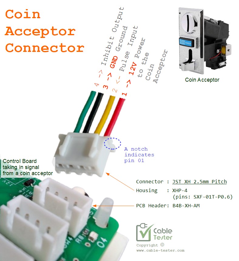
Pins of a Coin Acceptor
- 12V
- Pulse out (pulse)
- Gnd
- Inhibit (also known as the Counter pin, CNT)
Coin acceptor devices do not use much power. Usually, the power is tapped directly from the VMC (Vending Main Controller) board.
The pulse out can vary from device to device. Generally, the pulse width can be about 25 to 100ms. An analog coin accepts emits each pulse for each coin that is inserted through the slot. For the newer electronic version of the coin acceptor, each coin denominator can generate a different number of pulses. The VMC will then be able to count the pulses and determine the amount of coins that is collected from your vending customer.
This pulse line should be pulled to Vcc (which is 12V) by the VMC board. The coin acceptor contains a npn transistor which pull this line to the ground. So this pulse-out signal is typically an active low signal.
The last pin is the Inhibit function. Sometimes this 4th pin is known as the Counter pin in many of the documentation online. It is normally not in use, as the pulse output would be enough to know how much value in the coin is collected. For this inhibit pin, it is a signal sent from the VMC to the coin acceptor to tell the coin acceptor not to accept any more coins. It is typically active low as well. Send a low signal will activate the inhibit function.
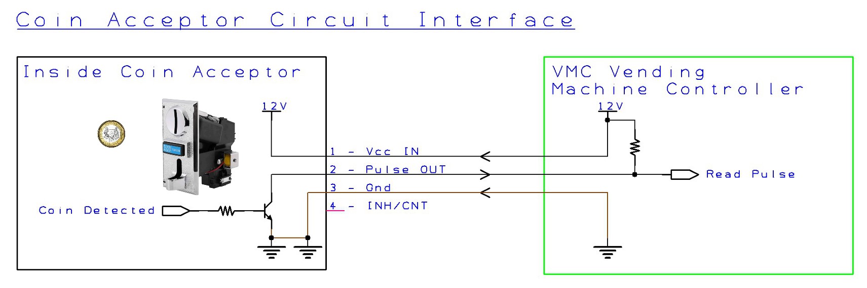
Coin Acceptor Interface Circuit & Signal
The interface to a coin accept is simple. Inside the coin acceptor’s pulse-out pin is a npn transistor. This npn transistor acts like a physical switch. When a coin is detected, this npn transistor is going to short the Pulse OUT line to the ground. When this happens, the VMC will be able to read the pulse line changing state. This pulse output is an active low pulse.