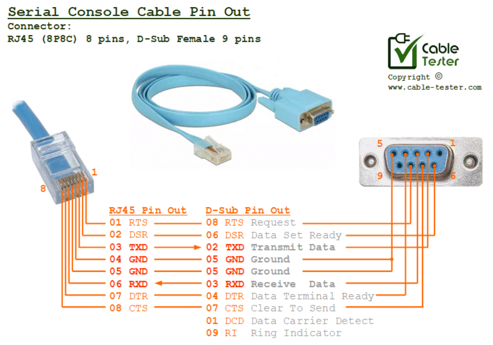
An RJ45 to RS232 console cable is used to connect a computer to a serial console port on a network device, such as a router, switch, or firewall. One end is connected to the server with RJ45 connector (8P8C, 8 pins), and the other end is to a computer with a D-Sub connector (female 9 pins, often known as d-sub09 connector)
A serial console cable is usually used for conveniently sending serial configuration commands to a server or equipment (usually Cisco equipment, often known as the Cisco Console Cable).
Serial Communication Setup
Typical communication baud rate setup for a serial console cable for Terminal Console.
- Baudrate: 9600bps
- Data bit: 8 bits
- Stop bit: 1 bit
- Parity: None
- No Hardware Handshaking
For a more detailed pin out of a typical RS232 cable, you can click here for more details.
Detailed RS232 D-Sub 9 Pins Description
In most applications, only pin 02 03 05 on the D-Sub 9 Pins connector is used for the RS232 application. This 3-wire communication mode is non-hardware-handshaking or asynchronous data communication. Meaning that the serial data is sent out based on a pre-set timing clock.
The rest of the pins are meant for controlling the flow of the data. Hardware handshaking (synchronous data communication) is slower. These are hardly used these days because of the faster processing power of IC chips and the timing precision that we have now. For most applications, you don’t need to wire up these wires. But we will still be presenting the purpose of these pins on the D-sub connector for complete documentation of the pin out.
- Pin 01 DCD – Data Carrier Detect (IN), indicator signal is detected from the remote terminal (the other end of the terminal).
- Pin 02 TXD – Transmitted Data (OUT), data sending out to the remote terminal.
- Pin 03 RXD – Received Data (IN), data coming in from the remote terminal.
- Pin 04 DTR – Data Terminal Ready (OUT), local terminal side is ready to receive data.
- Pin 05 GND – Signal Ground (COMMON), reference pin for all the signal pins.
- Pin 06 DSR – Data Set Ready (IN), remote terminal is ready to receive and send data.
- Pin 07 CTS – Clear To Send (IN), remote terminal is ready to receive data.
- Pin 08 RTS – Request To Send (OUT), the local terminal is requesting the remote terminal to send over data.
- Pin 09 RI – Ring Indicator (IN), the local terminal receives the ring from remote terminal.
Check out here for our universal Cable Tester project.