The DFRobot Gravity Series stands as a premium open-source electronics toolkit, designed to be modular, plug-and-play, and accessible to all. Featuring robust expansion shields, a diverse array of professional-grade functional modules boasting standard interfaces, and comprehensive documentation, the Gravity Series empowers users of any expertise level to effortlessly connect and combine components, bringing their ideas to life or advancing their projects with ease.
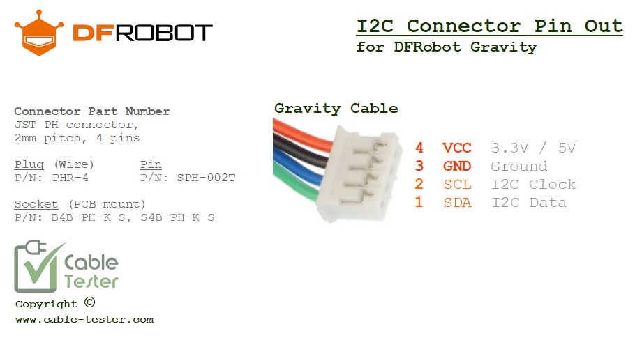
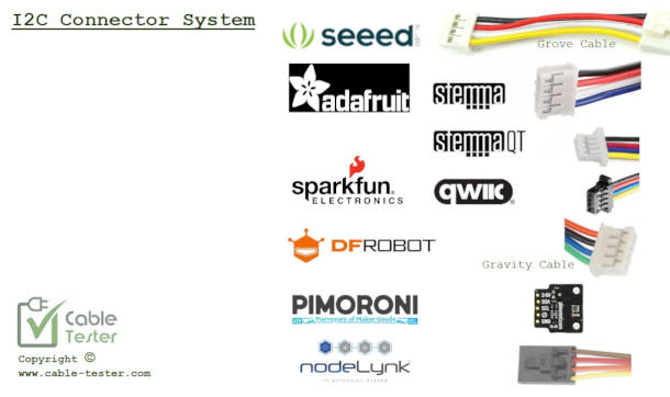
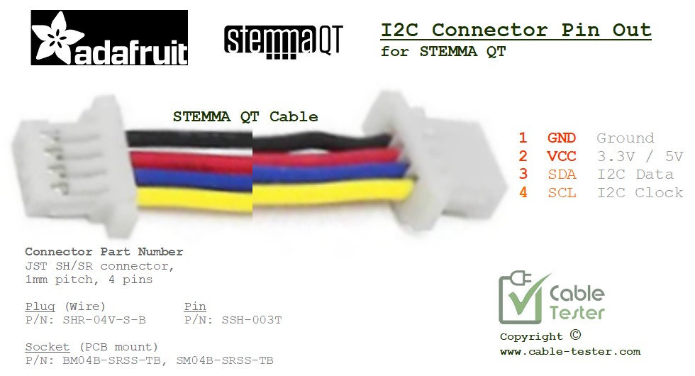
The I2C cable used for Gravity (DFRobot) is the same connector used for Grove (Seeed Studio) and Stemma (Adafruit), but however the pin out wiring is not the same. So while you can use the I2C cable, but you cannot mixed and inter-connect Gravity electronic board with the other brands. An adaptor cable is needed to do the signal line conversion.
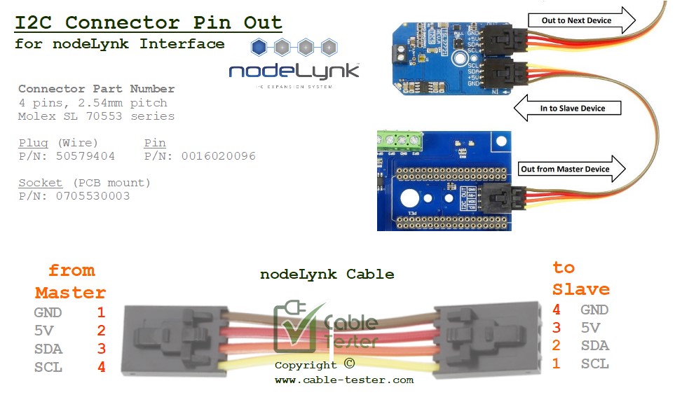
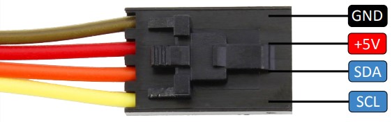
Gravity I2C connector details
Gravity I2C inter-connection system uses PH series from JST. JST specialises in connector product. The following is the datasheet and drawing for the JST PH series connectors use.
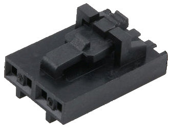
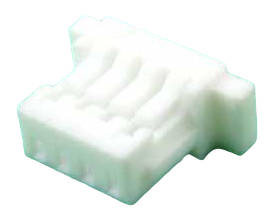
Cable Plug
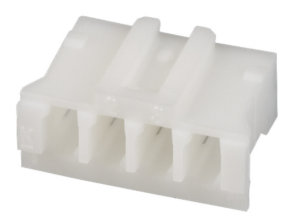
Housing part number: PHR-4
– Available from Digikey: 455-1164-ND
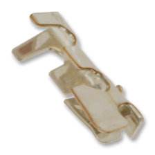
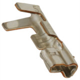
Crimp Pin part number: SPH-002T
– Available from Digikey: 455-1127
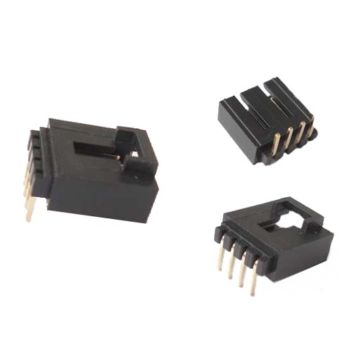
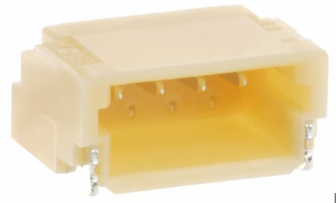
Board Socket
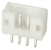
– Socket part number: B4B-PH-K-S (Available from Digikey: 455-1706-ND)
– Socket part number: S4B-PH-K-S (Available from Digikey: 455-1721-ND)
Tools Accessories
- Tool hand crimper 28-30AWG side, part number WC-240 (Available from Digikey: 455-1128-ND)
- TOOL EXTRACTION PH SERIES CONTAC, part number EJ-PH (Available from Digikey: 455-EJ-PH-ND)
Check out our best seller general purpose Cable Tester tool.
Other I2C Connector Standard.
You may also be interested in other i2c connector standard available on the market. Click here.