There are two typical RS232 cables used in industry.
- Crossed RS232 cable (or known as a null modem cable)
- Straight RS232 cable
RS-232 Cable Wiring: Crossed vs. Straight
When working with RS-232 serial communication, choosing the right cable wiring is critical. Some applications require a straight-through cable, while others need a crossed (null-modem) cable. This guide explains the difference, shows pin-outs, and provides troubleshooting tips.
DTE vs. DCE: Why Cable Type Matters in RS-232
Definitions:
- DTE (Data Terminal Equipment): Devices such as PCs, printers, terminals, and data loggers.
- DCE (Data Communication Equipment): Devices such as modems, routers, and multiplexers.
Connection Rules:
- DTE ↔ DCE: Use a straight-through cable.
- DTE ↔ DTE or DCE ↔ DCE: Use a cross (null-modem) cable.
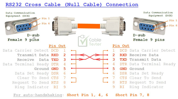
Cross Cable RS232 wiring
Cross-cable wiring for RS-232 usually occurs between two DCE (Data Communication Equipment) devices or two DTE (Data Terminal Equipment) devices.
Typically, for the connection between DTE↔DTE, DCE↔DCE devices,
TXD connects directly to RXD,
RXD connects directly to TXD.
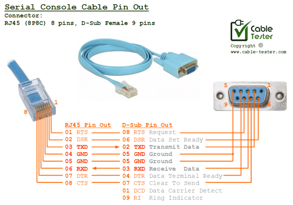
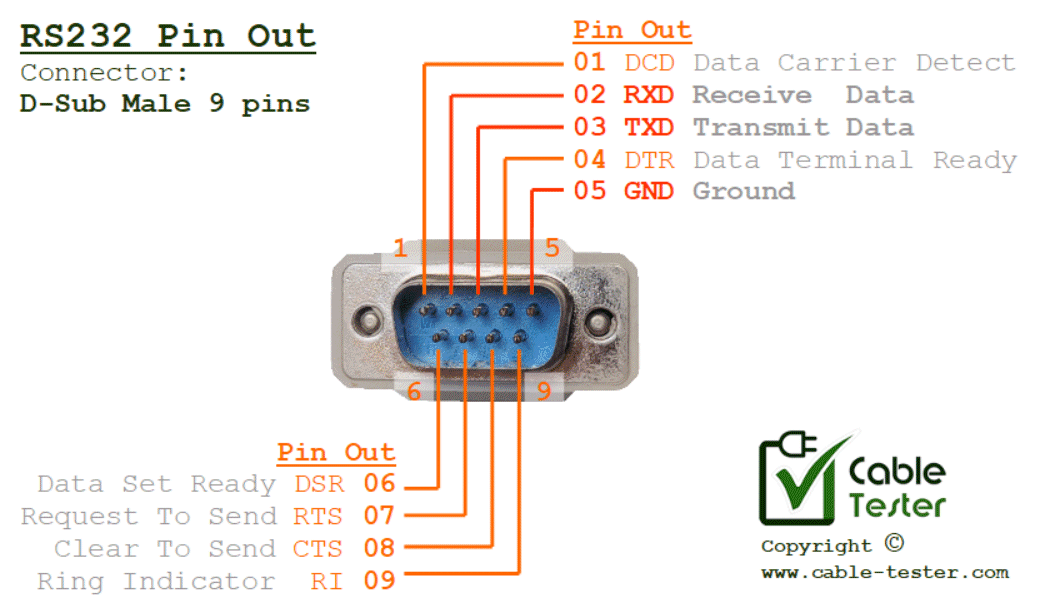
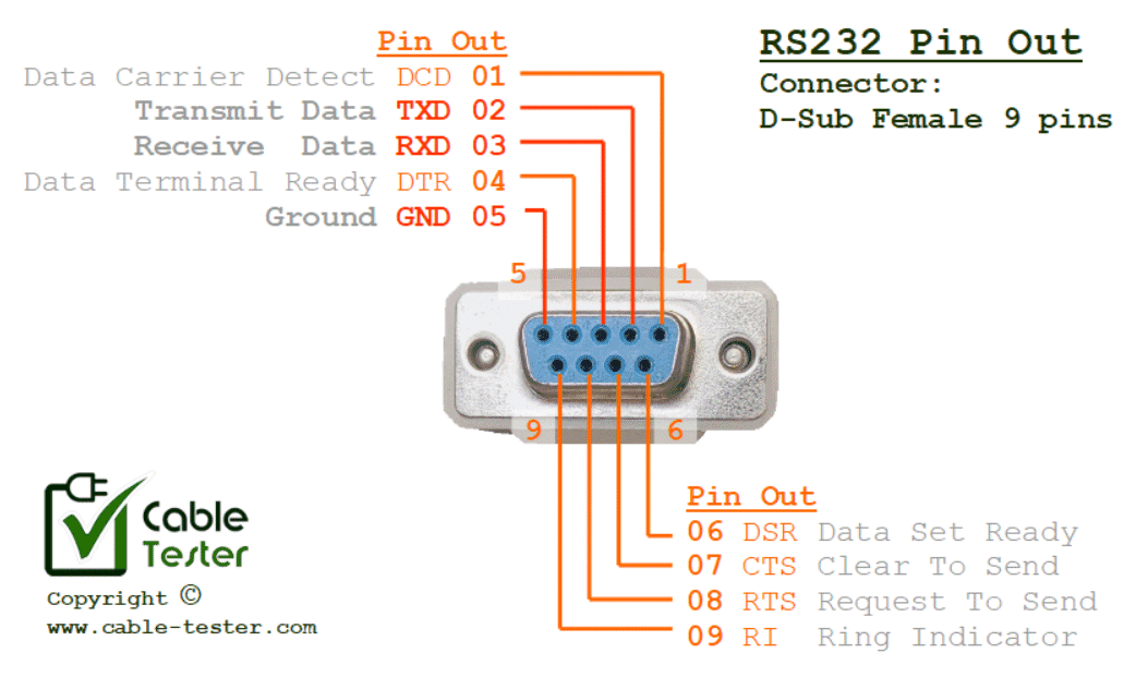
*** Click here for RS232 connector pinout (male/female).
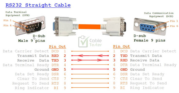
Straight Cable RS232 wiring
Typically, for the connection between DTE↔DCE devices,
TXD connects directly to TXD,
RXD connects directly to RXD.
*** Click here for RS232 connector pinout (male/female).
When to Use Each Cable
- Straight Cable: Connecting PC ↔ Modem, Router ↔ Terminal.
- Cross Cable: Connecting PC ↔ PC, Modem ↔ Modem, Router ↔ Router.
- If unsure, start with straight; if no communication occurs, try cross.
Troubleshooting RS-232 Connections
- No data or garbage characters → Check Tx/Rx wiring.
- Connection drops → Verify RTS/CTS or DTR/DSR control signals.
- Cable too long → RS-232 is limited to ~15m (50ft). Use shielded cable for reliability.
- Testing → Use a cable tester (like our CCT-01 Cable Connection Tester) to quickly verify wiring connections.
Cable Assembly Tips
- Use shielded cable to reduce noise.
- Ensure connectors (Dsub-9, Dsub-25) are securely crimped or soldered.
- Label cables clearly to avoid mix-ups.
- Keep cables under the recommended length for stability.
FAQs
Q: Can I convert a straight cable into a cross cable?
Yes — with an adapter (null-modem adapter) or by re-wiring.
Q: Do I need all pins connected?
Not always. Many simple RS-232 applications only require Tx, Rx, and GND.
Q: What’s the difference between DB-9 and DB-25?
Dsub-25 has more pins, historically used for extra control signals. Most modern RS-232 devices use Dsub-9.
Related Guides
- RS-232 Pinout Reference
- RS-232 vs RS-485: What’s the Difference?
- How to use a Cable Tester?