
Electrical Cable Size Guide

Correctly sizing electrical cables is a critical aspect of safe and efficient household wiring. The wrong cable size can lead to overheating, fire hazards, and energy losses. This guide provides a concise reference for selecting cable sizes in typical domestic applications.

Electrical Cable Size Guide for household (home)

For Household Installations

Importance of Cable Sizing

  • Safety: Prevents overheating and electrical fires.
  • Performance: Ensures voltage remains within acceptable limits.
  • Compliance: Meets regulatory standards and building codes.

Key Considerations

When selecting a cable size, take into account the following:

  1. Current Load (Amperage) – Based on the combined power rating of appliances or fixtures.
  2. Length of Run – Longer distances increase resistance; larger cable sizes may be required.
  3. Installation Environment – Thermal insulation, conduits, or direct burial affect heat dissipation.
  4. Voltage Supply – Most households operate at 230V (UK, EU, Asia) or 120V (North America).
  5. Local Regulations – National codes (e.g., NEC, IEC, IET Wiring Regulations) must be followed.

Common Household Cable Sizes

Cable Size (mm² copper)Max Current
(A)
Typical use with Circuit Breaker Current Rating (A)Typical Application
1.0 mm²10 ALightings
1.5 mm²17 A10 AFan, Lightings, Kettle, Fridge, Washing Machine
2.5 mm²24 A16 A15A 3 pins socket,
Iron, Shower water heater, Aircon, Dryer, Oven
4.0 mm²32 A20 ALooped wiring for 13A 3 pins socket, Aircon
6.0 mm²41 A32 AAircon, Cooking Stove
10.0 mm²57 A40 ACable size used for supply power to modern home.

⚠️ Note: These values are indicative only. Always confirm with local standards and appliance ratings.


Voltage Drop Reference

Excessive voltage drop reduces efficiency and may damage appliances.

  • Maximum recommended drop: 3% for lighting circuits; 5% for other circuits.
  • For long cable runs (e.g., outbuildings), select the next higher cable size.

Safety and Best Practices

  • Use cables conforming to certified standards (BS, IEC, UL).
  • Match protective devices (fuses, MCBs, RCDs) to the circuit rating.
  • Avoid overloading multiple devices on undersized circuits.
  • For upgrades or new installations, consult a licensed electrician.

Conclusion

Correct cable sizing is essential for safe, efficient, and compliant household wiring. While smaller circuits (lighting) require 1.0–1.5 mm² conductors, heavy-load appliances often demand 6.0 mm² or larger. Always verify requirements against national codes and specific appliance ratings before installation.
Free Cable Drawing Software

Check out these free cable design and management tools to manage your cable documentation and fabrication.

  1. Cable Design Tool (by Pickering Connect)
  2. anekonnect
  3. WireViz
  4. Rapid Harness
  5. E3.cable
  6. HarnWare Software
  7. WDT Wiring Harness Design Tool
  8. Unigraphics NX
  9. Capital
  10. Harness Builder
  11. WireCAD

Cable Design Tool

The Cable Design Tool by Pickering Connect is a free, innovative online platform designed to simplify the process of creating custom cable assemblies. This tool is particularly beneficial for engineers and designers looking to streamline their workflow from concept to final product.

Key Features

  • User-Friendly Interface: The Cable Design Tool is cloud-based and accessible via modern web browsers, making it easy to use on various devices, including tablets. Its graphics-based design allows users to visualize their cable assemblies in detail12.
  • Comprehensive Design Options: Users can customize their cable assemblies with a wide range of options, including:
    • Selection of connector types
    • Wire types
    • Pin definitions and labeling
    • Cable bundling and length specifications
    • Sleeving comments and more28.
  • Built-in Library: The tool features a library of standard cable sets, enabling users to start their designs from pre-existing templates or create entirely new configurations from scratch. This flexibility enhances the design process and saves time12.
  • Expert Support: For users who encounter challenges during the design process, Pickering offers support from experienced engineers. Users can submit semi-completed designs for guidance, ensuring they receive expert assistance when needed26.

Benefits

  • Cost-Effective Solution: As a free tool, it eliminates the financial barriers often associated with professional design software. This makes it accessible for businesses of all sizes, from startups to established manufacturers17.
  • Streamlined Workflow: The tool facilitates a smooth transition from design to production. Once the design is complete, users can easily submit it for a quote, simplifying the procurement process18.
  • Quality Assurance: All products designed through the Cable Design Tool come with a robust three-year warranty, reflecting Pickering’s commitment to quality and reliability. The manufacturing processes adhere to international standards, ensuring that all assemblies meet strict performance and safety regulations17.

Conclusion

The Cable Design Tool by Pickering Connect stands out as an essential resource for anyone involved in cable assembly design. Its combination of user-friendly features, comprehensive customization options, and expert support makes it an invaluable asset for engineers and designers alike. Whether you are looking to create a simple cable assembly or a complex custom solution, this tool provides the resources you need to bring your ideas to life efficiently and effectively.

https://www.youtube.com/watch?v=6DLbEmezSgM&list=PLAo_E_MyiEatxpyyl2cM5ArAPwNwbZsxx

anekonnect

https://anekonnect.io

WireViz

WireViz is an open-source tool designed for documenting cables, wiring harnesses, and connector pinouts. It uses plain text YAML-formatted files as input and generates visually appealing graphical outputs, including SVG and PNG formats. Key features include:

  • Automatic Bill of Materials (BOM) generation.
  • Support for various wire color schemes and gauge calculations.
  • Easy version control due to its text-based input files.
  • Compatibility with GraphViz for creating diagrams.

This software is still pretty raw. There is no user interface and to use it, you will need to know how to setup. More technical knowledge is required before you can start to use it.

Introduction

How to design custom cable using WireWiz

Setting up WireViz

WireWiz tutorial setup video

Reference

Rapid Harness

Wiring Harness Software

https://rapidharness.com

E3.cable

https://www.e3seriescenters.com/electrical-wiring-design-software/electrical-harness-design-software/e3-cable

HarnWare Software

Wiring Harness Drawing Builder

https://www.te.com/en/products/wire-protection-and-management/harness-software-harnware.html

WDT Wiring Harness Design Tool

https://ggmotorsport.co.uk/wiring-design-tool-wdt

Unigraphics NX- Electrical Routing/Wiring and Harness (by Siemens)

Capital™ Wiring Designer Essentials and Capital™ Harness Designer Essentials tools

Capital capabilities
Wiring harness design and engineering

https://trias-mikro.de/en/solutions/mainstream-harness-design

Capital Harness XC

https://www.youtube.com/watch?v=1Dr4n6XMHsY

Harness Builder (Zuken)

Simplify Wire Harness Design and Manufacturing

WireCAD

https://wirecad.soft112.com/#google_vignette

CAN Bus connector pin out

CAN bus (Controller Area Network bus), now widely used in the automotive industry, factory machine automation, medical industry, etc… Often you will come across a CAN bus cable and connection.

The underlaying physical signal of the CAN bus is actually the same differential signal on RS485/RS422. CAN bus value-add with the data communication protocol running on the RS485 kind of physical wires.

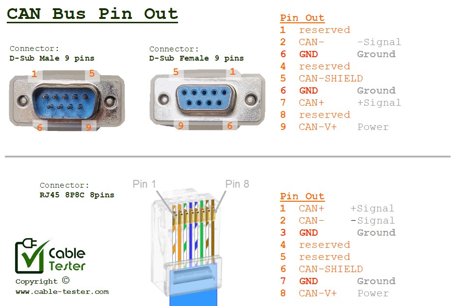
CAN Bus pin out (for D-sub09 male/female connector, for RJ45 8P8C connector)

There are various cable and connector standard using CAN Bus protocol. Some system uses D-sub09 male/female connector, some uses RJ45 8P8C jack. There are also CAN Bus implemented on XLR 4 pins connector, as well as . Power supply on the CAN Bus system can be 12V/24V. It depends on the system implementing the CAN Bus.

Connector pin out: D-sub09 (male/female)

  1. reserved
  2. CAN-
  3. GND
  4. reserved
  5. CAN-SHIELD
  6. GND
  7. CAN+
  8. reserved
  9. CAN-V+

Connector pin out: RJ45 (8P8C jack)

  1. CAN+
  2. CAN-
  3. GND
  4. reserved
  5. reserved
  6. CAN-SHIELD
  7. GND
  8. CAN-V+

Connector pin out: XLR 4 pins

  1. 24V
  2. CAN+
  3. CAN-
  4. GND

Connector pin out: M12 Circular Connector 5 pins

  1. CAN-SHIELD
  2. 24V
  3. GND
  4. CAN+
  5. CAN-

Background about CAN Bus

It was initially developed by Bosch in the mid-1980s to address the complex wiring harnesses found in modern vehicles, which were becoming increasingly complex due to the introduction of advance electronic control units (ECUs) and sensors. It is a communication standard designed for the vehicle industry to allow microcontrollers and devices to communicate with each other within a vehicle without a host computer.

The primary goal of the CAN bus was to reduce the amount of wiring needed in vehicles while providing a reliable communication protocol for various vehicle systems, such as engine management, transmission control, anti-lock braking systems (ABS), airbag systems, and more.

Key features of the CAN bus include:

Differential Signaling: CAN bus uses a differential signaling scheme, where data is transmitted as a voltage difference between two wires (CAN-High and CAN-Low). This provides immunity to noise and interference, making CAN bus communication reliable in noisy automotive environments.

Multi-Master: CAN bus allows multiple nodes (ECUs or devices) to transmit and receive data on the bus simultaneously. This is facilitated by a non-destructive arbitration mechanism where messages with higher priority are given precedence on the bus.

Deterministic Communication: CAN bus provides deterministic communication, meaning that messages are transmitted and received with predictable timing. This is essential for real-time control applications in vehicles.

Error Detection and Fault Tolerance: CAN bus incorporates built-in mechanisms for error detection and fault tolerance. Each message sent on the bus includes a cyclic redundancy check (CRC) to detect errors, and the protocol supports error handling mechanisms such as automatic retransmission of corrupted messages.

CAN bus has become the industrial standard for in-vehicle networking due to its reliability, simplicity, and cost-effectiveness. It has been widely adopted across the automotive industry and is also used in various other applications beyond automotive, including industrial automation, medical devices, and more. Over time, the CAN bus standard has evolved, with newer versions introducing enhancements such as higher data rates and improved error handling capabilities.

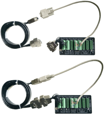
Check out our best seller general purpose Cable Tester tool.