CAN bus (Controller Area Network bus), now widely used in the automotive industry, factory machine automation, medical industry, etc… Often you will come across a CAN bus cable and connection.
The underlaying physical signal of the CAN bus is actually the same differential signal on RS485/RS422. CAN bus value-add with the data communication protocol running on the RS485 kind of physical wires.
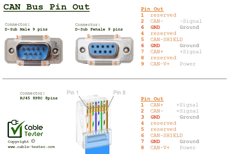
There are various cable and connector standard using CAN Bus protocol. Some system uses D-sub09 male/female connector, some uses RJ45 8P8C jack. There are also CAN Bus implemented on XLR 4 pins connector, as well as . Power supply on the CAN Bus system can be 12V/24V. It depends on the system implementing the CAN Bus.
Connector pin out: D-sub09 (male/female)
- reserved
- CAN-
- GND
- reserved
- CAN-SHIELD
- GND
- CAN+
- reserved
- CAN-V+
Connector pin out: RJ45 (8P8C jack)
- CAN+
- CAN-
- GND
- reserved
- reserved
- CAN-SHIELD
- GND
- CAN-V+
Connector pin out: XLR 4 pins
- 24V
- CAN+
- CAN-
- GND
Connector pin out: M12 Circular Connector 5 pins
- CAN-SHIELD
- 24V
- GND
- CAN+
- CAN-
Background about CAN Bus
It was initially developed by Bosch in the mid-1980s to address the complex wiring harnesses found in modern vehicles, which were becoming increasingly complex due to the introduction of advance electronic control units (ECUs) and sensors. It is a communication standard designed for the vehicle industry to allow microcontrollers and devices to communicate with each other within a vehicle without a host computer.
The primary goal of the CAN bus was to reduce the amount of wiring needed in vehicles while providing a reliable communication protocol for various vehicle systems, such as engine management, transmission control, anti-lock braking systems (ABS), airbag systems, and more.
Key features of the CAN bus include:
Differential Signaling: CAN bus uses a differential signaling scheme, where data is transmitted as a voltage difference between two wires (CAN-High and CAN-Low). This provides immunity to noise and interference, making CAN bus communication reliable in noisy automotive environments.
Multi-Master: CAN bus allows multiple nodes (ECUs or devices) to transmit and receive data on the bus simultaneously. This is facilitated by a non-destructive arbitration mechanism where messages with higher priority are given precedence on the bus.
Deterministic Communication: CAN bus provides deterministic communication, meaning that messages are transmitted and received with predictable timing. This is essential for real-time control applications in vehicles.
Error Detection and Fault Tolerance: CAN bus incorporates built-in mechanisms for error detection and fault tolerance. Each message sent on the bus includes a cyclic redundancy check (CRC) to detect errors, and the protocol supports error handling mechanisms such as automatic retransmission of corrupted messages.
CAN bus has become the industrial standard for in-vehicle networking due to its reliability, simplicity, and cost-effectiveness. It has been widely adopted across the automotive industry and is also used in various other applications beyond automotive, including industrial automation, medical devices, and more. Over time, the CAN bus standard has evolved, with newer versions introducing enhancements such as higher data rates and improved error handling capabilities.