This wire type is usually for DC power supply wire. The black wire with a white stripe is typically a negative terminal.
Don’t risk damaging your device—learn the safe way to identify polarity and connect your power supply correctly.
Here’s how to safely find its polarity, before you power up your device.
Is it Positive or Negative terminal?
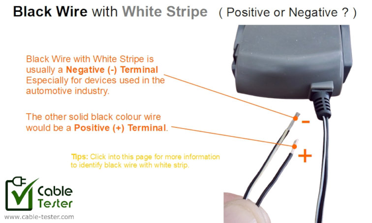
If you’re dealing with a device that has a black wire with a white stripe (may be solid or dashed white line), you may be wondering: which terminal is positive and which is negative?
The truth is: there is no universal standard. Different industries and manufacturers may use this wire differently. However, certain conventions exist in specific fields: automotive, industrial, consumer electronics, and more. Because of this variability, never rely on wire colour alone.
The safest way to determine polarity is to follow the manufacturer’s documentation. If there is no documentation, we may determine it through a conventional standard or test it with a multimeter. The following are some possible ways to identify the wire polarity.
Industry Conventional Standard
Certain industries and applications have their own conventions. For example:
In automotive 12V DC systems, the black wire with a white stripe is often negative (ground), while the solid black wire is positive.
In industrial, telecommunications, and consumer electronics, the stripe may indicate a ground, return, or reference conductor—but the exact meaning varies by system.
Because of this variability, you should never rely on wire colour alone. Using a multimeter or consulting the device documentation is the safest way to identify polarity and prevent damage.
Here is a quick guide on the usual industry conventional standard. You have to base your judgment, as it is not a universal colour code standard.
Industry Conventional Reference Guide
| Industry / Application | Black Wire with White Stripe | Solid Black Wire | Notes / Variability |
|---|---|---|---|
| Automotive (12V DC) | Negative (-) / Ground | Positive (+12V) | Most common convention in cars, trucks, motorcycles |
| Industrial Automation | Usually Negative (-), sometimes Positive (+) | Usually Positive (+), sometimes Negative (-) | Depends on system and manufacturer; often a reference or signal line |
| Telecommunications (–48V DC) | Usually Positive (+), can be Negative (-) depending on the local wiring standard. | Usually Positive (+), can be Negative (-) depending on local wiring standard. | In telecom DC power systems, polarity may be reversed |
| Consumer Electronics | Negative (-) | Positive (+) | Typical in LED drivers, adapters, battery-powered devices; manufacturer-dependent |
| Security & Fire Alarm Systems | Negative (-) | Positive (+) | Used in CCTV, sensors, alarm panels; usually negative but can vary |
| Renewable Energy (Solar / Batteries) | Negative (-) | Positive (+) | Stripe usually marks negative, but BMS and controller designs may differ |
| Marine (Boats, Yachts) | Negative (-) | Positive (+) | Often follows automotive convention, but always verify |
| Aerospace / Avionics | Negative (-) | Positive (+) | Military and aerospace standards may use striped black differently; always check schematics |
| Railway & Transportation | Negative (-) | Positive (+) | Polarity can vary; trace wires to verify |
| Medical Devices (Low-voltage DC) | Negative (-) | Positive (+) | Usually internal power wiring; verify with documentation |
Black Wire with White Stripe is Usually the Negative Terminal
The black wire with a white stripe typically serves as the reference ground or negative terminal in most systems. Assuming the striped black wire is negative is often correct, especially in automotive and common DC applications.
Industries Where Black Wire with White Stripe May Be Positive
In some industries, the black wire with a white stripe can be defined as a positive terminal. The table below summarizes key examples where this convention may occur, highlighting the importance of verifying polarity before connecting any device.
1. Telecommunications (–48V DC systems)
- Telecom systems often use –48V DC for powering equipment.
- In some setups, the black wire with white stripe can carry positive voltage, while the solid black wire may serve as negative return.
- This is industry-specific and depends on the telecom provider or local wiring standards.
2. Industrial Control & Automation (certain systems)
- Some control panels or sensor wiring may use the striped black as a signal or positive supply instead of ground.
- Example: DC sensors or actuators in machinery where the solid black is reserved for ground reference.
3. Custom / Proprietary Devices
- Some battery-powered or low-voltage electronics may define the striped black as +, depending on the manufacturer’s design.
- Examples include drones, specialty instruments, or aftermarket electronics where “black” is not exclusively tied to ground.
Wire Strands Material / Colour
While this method is also not a standard, there is some following this standard to differentiate between a positive wire or a negative wire.
Copper vs. Silver: If the wires are different colours inside the insulation, the copper-colored wire is typically Positive, and the silver-colored wire is Negative.
Test with a Multimeter
This is a bit technical, and requires some basics in electronics.
Method 1: Ground connected to metal parts on the casing
One tip for a device which has a metal enclosure or metal external parts, the ground wire may be connected to these metal parts. You can use a multimeter continuity function to check which wire is connected to the metal parts of the device. The wire that is connected to the metal part is likely to be the ground reference (negative terminal).
Method 2: The Diode Test (The “One-Way Street”)
Many 12V devices have a “Protection Diode” at the input to prevent damage from reverse polarity. You can use this to find the “correct” path.
- Set to Diode Mode: Turn the dial to the Diode symbol ($\rightarrow|$).
- Test Direction A: Touch the Red probe to Wire 1 and the Black probe to Wire 2. Note the reading (it might say “OL” or show a number like 0.500).
- Test Direction B: Swap the probes (Red to Wire 2, Black to Wire 1).
- The Result: * If you see a reading between 0.400 and 0.900 in one direction and “OL” in the other, the device has a protection diode.
- In the direction that shows a number (conducts), the Red probe is touching the Negative (-) wire and the Black is touching the Positive (+). (This is because the diode is usually placed “backward” across the input to short out reverse current).
Method 3: Capacitance / Visual Inspection
If you can see the circuit board inside:
- Look for an Electrolytic Capacitor: These are the small “can-shaped” components. They are strictly polarized.
- Identify the Stripe: One side of the capacitor will have a wide stripe with minus signs (- – -).
- Trace the Path: Use the Continuity setting to see which of your two mystery wires is connected to the side of the capacitor with the minus stripe. That wire is your Negative (-) wire.