DIN08 Pinout Guide
A DIN08 plug is a full-size 8-pin circular DIN connector used in cable assemblies, legacy equipment, control systems, medical call accessories, and custom interfaces.
This guide shows the face side pin numbering for a standard DIN08 male plug and explains why the connector view direction must always be stated clearly.
Test DIN08 Cables with CCT-01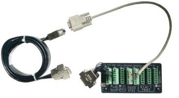
What is DIN08?
DIN08 usually refers to a full-size 8-pin circular DIN connector. The connector body defines the mechanical format, but the actual electrical function of each pin depends on the product, system, or manufacturer.
Same Plug Shape
The connector can look physically the same across many devices.
Different Pin Functions
Pin 1 to Pin 8 may be assigned differently depending on the application.
Must Verify
Always check the equipment drawing, manual, or continuity test result before wiring.
Correct DIN08 Pin Numbering – Male Plug Face Side
The diagram below shows the front face / mating side of a male DIN08 plug. This is the side you see when looking directly at the plug pins before inserting it into the socket.
Male DIN08 Plug – Face Side View
How to Read This View
This diagram shows the male DIN08 plug from the front. You are looking directly at the pins that go into the socket.
Face Side vs Solder Side
Many DIN08 wiring mistakes happen because the drawing does not clearly state which side of the connector is being viewed.
Face Side / Mating Side
This is the front of the plug. It is the side with the visible pins that enter the socket.
The realistic diagram above uses this view.
Solder Side / Wiring Side
This is the rear side of the connector, where wires are soldered to the terminals.
This side is normally mirrored compared with the face side.
“DIN08 male plug – face side / mating face view.”
DIN08 Pinout is Application Specific
The DIN08 connector layout only defines where the pins are physically located. It does not define what each pin is used for.
Common DIN08 Application Pinouts
DIN08 connectors can be found in different industries and equipment types. The table below gives common application examples, but the actual pin assignment must always be verified.
| Application | Typical Signals | Important Note |
|---|---|---|
| Straight-through extension cable | Pin 1→1, 2→2, 3→3, 4→4, 5→5, 6→6, 7→7, 8→8 | Common for simple extension or adapter harnesses. Confirm shield or shell connection too. |
| Industrial control cable | Power, common, digital input, digital output, analog signal, enable, alarm, or sense | Electrical function is equipment-specific. Do not assume voltage or polarity. |
| Audio / video equipment | Audio, video, sync, switching, or ground | Legacy equipment often uses custom DIN08 assignments. |
| Lighting control | Control channels, reference, supply voltage | Older analog lighting systems may use DIN08, but wiring varies by brand. |
| Medical / call button accessories | Switch contacts, LED, lamp, buzzer, common, call line, data, or sense | Never assume compatibility just because the plug fits mechanically. |
| Custom cable assemblies | Any user-defined combination | Create a clear pin-to-pin table and test every production cable. |
Recommended DIN08 Wiring Documentation Format
For fabrication, purchasing, or troubleshooting, document the cable using a clear pin mapping table.
| DIN08 Pin | Signal Name | Wire Colour | Connects To | Remark |
|---|---|---|---|---|
| Pin 1 | Signal / Function | Black | _____ | Confirm continuity |
| Pin 2 | Signal / Function | Red | _____ | Check polarity if power is involved |
| Pin 3 | Signal / Function | White | _____ | Application-specific |
| Pin 4 | Signal / Function | Green | _____ | Application-specific |
| Pin 5 | Signal / Function | Blue | _____ | Application-specific |
| Pin 6 | Signal / Function | Yellow | _____ | Application-specific |
| Pin 7 | Signal / Function | Brown | _____ | Application-specific |
| Pin 8 | Signal / Function | Shield / Other | _____ | Center pin |
How to Check a DIN08 Cable
- Confirm whether the drawing is face side or solder side.
- Confirm whether the connector is male or female.
- Confirm whether the connector is the correct DIN08 variant for the equipment.
- Map each wire using continuity testing.
- Check for shorts between adjacent pins.
- Record the final pin-to-pin mapping in a table.
- Keep one verified master cable as the production reference sample.
Testing DIN08 Cables with CCT-01
For custom DIN08 cable assemblies, a cable tester helps verify that each production cable matches the approved master cable. This helps detect wrong wiring, open circuits, and short circuits quickly.
1. Connect
Connect the DIN08 cable to your fixture or breakout interface.
2. Learn
Use a known-good cable as the master reference.
3. Test
Compare production cables quickly and consistently.
Need to Verify a DIN08 Cable Pinout?
Confirm the exact connector view, document the wiring clearly, and test every cable against a verified reference before installation or shipment.
View CCT-01 Cable Connectivity Tester