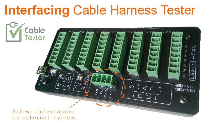
This cable tester CCT-01 is design for interfacing with external system in mind. It allows you to interface with machine for testing automation process, or it can be to external switch/sensor and indicators that suits your environment. This makes the CCT-01 scalable and flexible for any sort of testing setup.
Interface Features
- External system control for testing automation.
- Scalable to test up to infinite number of wiring connection. (*note #1)
- Custom your own operator’s user interface hardware.
- Connection to digital controller.
- Connection to high power appliances.
Content (Quick access links)
- Interfacing Cable Harness Tester
- External User Interface to Cable Tester
- External LEARN Button
- Linking up Multiple Cable Tester
- Cable Tester Connection to Digital Controllers
- Interfacing Cable Tester to High Power Devices
Interfacing Cable Harness Tester
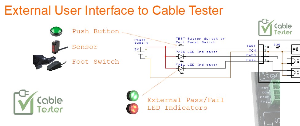
External User Interface to Cable Tester
The following diagram illustrate an example of connecting your own operator’s hardware to control the CCT-01 Cable Tester.
For interface connection to high power appliances, please check out the section further down below on “Interfacing Cable Tester to High Power Devices“.
A simple video example of interfacing to cable tester
This is a custom tester setup from our customer. Using the interface features of CCT-01 Cable Tester to custom built a tester that is suitable for their automation application.
The external interfacing on the cable tester allows you with a lot of flexibility to design and custom build a tester that fits your testing work flow.
External LEARN button
For user who wants to extend the LEARN as an exter
This was not the design intent for CCT-01 Cable Connection Tester, as the LEARN button can over-write the internal saved memory of your original Master Cable connection.
There were some enquiries asking for a way to extend this button externally. We decided to make things easier for such applications.
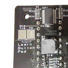
For the new CCT-01 Cable Connection Tester (production batch after the date of June 2024), we have designed 2 big pads for users to solder an external physical push button switch for use as a LEARN button.
These two pads are found just right behind the LEARN button. You have to open up the cable tester to locate these 2 pads. They are pretty big and properly labelled.
For the earlier batch, there are no such solder pads available. You can still extend out to an external physical push button switch.
You can solder to the IC chip U10, pins 13 and 14. The available space for soldering is limited and it is pretty challenging to solder.
Linking up Multiple Cable Tester
The CCT-01 Cable Tester is design for the testing of 64 connection points. If you need to test a larger sets of more than 64 connection points, it is possible to link up multiple CCT-01 Cable Tester together. There is no limit to how many CCT-01 Cable Tester that you can use. This means that you can potentially scale up the tester and test up to infinite number of connection points using only CCT-01.
*note #1: The only point you need to note is to ensure that the wiring that is suppose to have connection with one another has to be all terminated on the same set of CCT-01 Cable Tester unit.
The following diagram illustration how you can use 3 sets of CCT-01 Cable Tester to test for cable connections of up to 192 connection points.
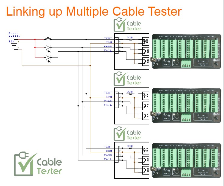
A single external momentary push button switch is connector to the 3 sets of cable tester in parallel. A single press on this switch will trigger the 3 sets of cable tester to start their individual connection point testing.
The two external LED indicator (Pass or Fail) will light up accordingly. If the cable test on all the 3 sets of CCT-01 is a pass, only the external PASS indicator gets to light up, the FAIL indicator will not light up. If both PASS and FAIL indicator lights up, it means that one or more CCT-01 tester found some connection fault on the cable. If only the FAIL indicator lights up, it means that all the tester found some connection fault on the cable.
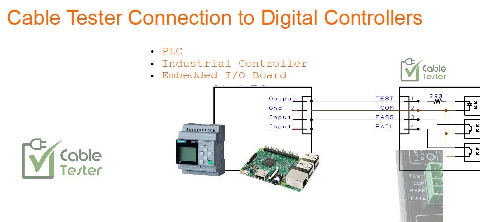
Cable Tester Connection to Digital Controllers
You can interface CCT-01 Cable Tester directly to your digital controller. Examples of digital controllers are like PLC (Programmable Logic Controller), Industrial PC Controller or Embedded I/O Board system.
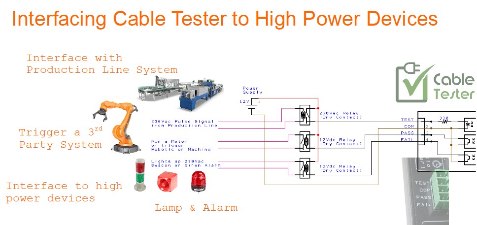
Interfacing Cable Tester to High Power Devices
You may also want to interface the controller to high power appliances rated 230Vac or 12Vdc and above. The following shows how you can connect and control those devices through an interfacing relay.
With this interface setup, you can control high power appliances like motors, bright electrical lamps, heaters, etc…
For more product information about CCT-01 Cable Tester, check out the following link.