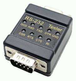
Connect this easy to use RS232 data link tester in between your RS232 data cable, and visually see that data is physically transmitted and received via the RS232 cable.
Features
No power required.
Standard RS232 DTE & DCE interface
DB9 Male to DB9 Female (Dsub 9 pins).
Easy to see 2 color LED indicators. Green LED is TTL out 1, Red LED is TTL out 0.
Reference pinout diagrams for DB9 connector (sometimes known as DE9 connector or D-sub connector) for RS232 serial communication ports. RS232 is a serial data communication signaling protocol. D-sub 9pins or 25pins connector is commonly used for RS232. These days RJ45 (or 8P8C) modular connector is also commonly used for RS232 purposes.
Note: For 3 wires RS232 serial communication (non-hardware-handshaking or asynchronous data communication) wiring, you only need pin 2, 3 (RX, TX), and pin 5 (Gnd)
Typically the TX pin of an RS232 D-sub connector represents data flowing out of the connector, flowing into the RX pin of its mating connector. This is a communication channel between two devices.
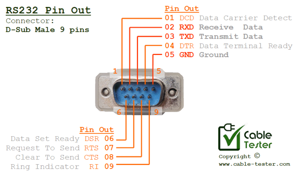
Male (D-Sub 9 pins)
The pin out of an RS232 male connector/socket, typically use on a computer terminal (DTE, Data Terminal Equipment)
RS232 Male Pin Out (D-sub 9 pins)
Note: Most systems use only 3 wires for asynchronous data communication. In those cases, only pin 02 RXD, pin 03 TXD, and pin 05 GND are important. The rest are not so important. Refer to crossed RS232 cable for more information.
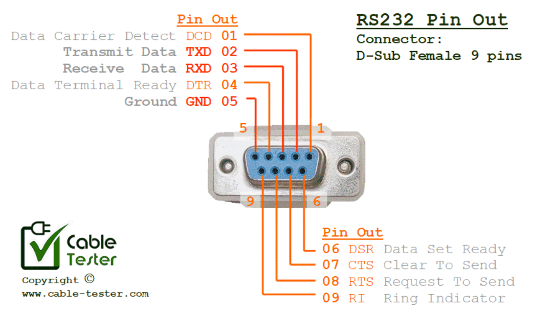
Female (D-Sub 9 pins)
The pin out of an RS232 female connector/socket typically used on an electronic device (DCE, Data Communication Equipment)
RS232 Female Pin Out (D-sub 9 pins)
Note: Most systems use only 3 wires for asynchronous data communication. In those cases, only pin 02 TXD, pin 03 RXD, and pin 05 GND are important. The rest are not so important. Refer to crossed RS232 cable for more information.
RS232 D-Sub Connector Information
D-Sub 9 pins male connector for RS232 is typically used on a computer terminal device (master). D-Sub 9 pins female connector for RS232 is typically used on an electronic device (slave).
RS232 standard was also implemented using a D-Sub 20pins connector. Nowadays is quite rare to use such a big connector.
The modern computer system uses RJ45 modular plug for its RS232 data communication. A common IT terminal console cable is known as “RS232 DB9 to RJ45”. This is typically for accessing the terminal console of IT equipment. Click here for more information about this cable.
Another common type of cable where RS232 is found is the “USB to RS232 converter cable“. Modern computing hardware uses USB connection more, due to its size and plug-and-play feature. It is commonly used between modern computer and industrial devices that still uses the RS232 communication method.
Typical RS232 Wire Connection (D-sub 9 pins)
RS232 cable typically has two types.
Crossed RS232 cable (or known as null modem cable)
The RS232 often uses a data baud-rate of 9600bps. This baud-rate is low and the cable length distance can be up to about 150 meters (about 500ft).
As the speed of data transmission increases on the cable, the physical signal of the data can easily be coupled to the adjacent wire. This induces noise onto the cable. The noise can be in the form of garbage data on the adjacent data wire. To reduce the effect of induced noise from the adjacent wire, the length is kept shorter. The insulation between wires is capacitance which high-frequency signals can easily pass over. The shorter length will keep the capacitance lower which makes it harder for the higher-frequency signal to be coupled over to the adjacent cable.
The following table is a general guide to the cable length base on the baud-rate. Please note that this is only a general guide. The material and the construction of the cable also play a part in the length of the cable. To be safe, it is better to have a margin factor of 2. If you really want to stretch the cable length further, ensure that you get yourself a high-quality RS232 cable and also use a better serial data protocol to detect data corruption and do the necessary data re-transmission.
Cable Length
Cable Length
Baud Rate
(in Metres)
(in Feets)
2400 bps
900m
3000ft
4800 bps
300m
1000ft
9600 bps
150m
500ft
19200 bps
15m
50ft
115200 bps
5m
16ft
RS232 Cable Length to Data Baud-rate table reference guide
You can easily do an experiment to see the effect of noise induced on the adjacent wire. Set up 3 wires (Tx, Rx, Gnd) of 30m to 50m distance between two RS232 devices (or computer). Have the wire twisted or taped up so that the gap between the wires is as small as possible. The best is no gap between the wires. Set up the baud-rate to 19200bps (with hardware handshaking).
Transfer a string of bytes into the Tx wire and observed the garbage bytes returning from the Rx wire. These garbage data are signals from the Tx wire coupled to the Rx wire. The disturbance noise triggered the receiver circuit thinking that a valid physical RS232 signal is received. These mis-triggered bytes received on the Rx channel are the noise induced from the Tx line. Change the baudrate lower to 9600bps. You will notice that the probability of this garbage generated is lesser or none. Increasing the baud-rate will also increase the probability of noise-induced.