Simple one button test for a quick, instant test result.
A circuit board tester to verify if the production board is functional.
Introduction
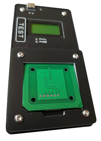
This is a custom circuit board tester for RFID board. Operator simply place the PCB board onto the placement jig and start the testing. The tester can auto detect the board and proceed testing the RFID board.
- Test RFID Reader circuit board
- Detects and read RFID Tag ID
There are testing instruction and video demonstration on this page to guide operator in using this circuit board tester device.
Parts & Description
Tester Package Content
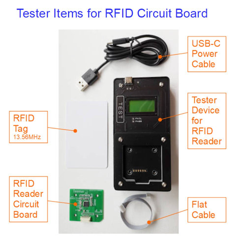
The tester set consist of main 5 items.
- RFID Circuit Board Tester
- RFID Reader Circuit Board
- USB-C cable
- RFID Tag
- Flat Cable for RFID Board
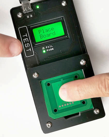
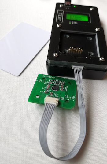
Tester
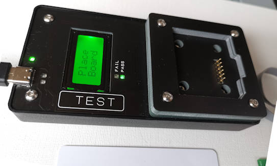
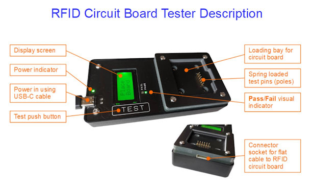
This test is easily powered up with a USB-C cable detect to support the testing of the RFID Reader circuit board.
There are two ways to test the board. Either by using the spring loaded contact pins, or using the 6 ways JST ZH cable.
The picture on the left provides a basic description of the tester’s device.
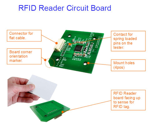
RFID Reader Circuit Board
The RFID Reader circuit board reads RFID tags.
Communication is using I2C through a JST ZH flat cable (6pos, 1.5mm pitch) to a controller board.
RFID Tag
The tester is programmed to read only Mifare Classic tags. For RFID Tag, you can use the following RFID tags.
- Mifare Mini S20 (320 bytes)
- Mifare S50 (1 Kbytes)
- Mifare S70 (4 Kbytes)
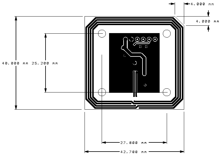
Physical Dimension of RFID Reader Circuit Board
The board is small at about 40 x 43mm. It has 4x mount hole size at ø3.2mm for M3 screw mounting. One of its corner is chambered as a marker to ensure that the board orientation is correct when position itself onto the tester device.
Testing Procedure for RFID Reader
- Power up the tester using the USB-C cable.
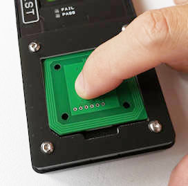
- Place the RFID Reader circuit board onto the tester.
Take note of the corner marker for the correct board orientation. Press the board slightly with finger to ensure that the 6x spring load pins get contact with the RFID reader board. - Using another finger, press in the TEST push button.
- The tester will first detect the presence of circuit board.
- The tester will then test to check if the reader circuit board is able to test read a RFID tag. Remember to present a RFID tag on top of the RFID reader board.
- The RFID tag ID is displayed for verification if it can be detected by the RFID Reader.
- Test is PASSED.
Video Demonstration 1 – Successful Testing Procedure
Click the video to playback.
The video demonstrates the complete process of testing the RFID Reader circuit board.
Video Demonstration 2 – No RFID Tag Detected
Click the video to playback.
The video demonstrates the same process but without any RFID tag presence. The board is detected and test is passed.
Video Demonstration 3 – No RFID Reader Board Detected
Click the video to playback.
This is a negative demonstration. The tester could not detect the board or if the board is faulty. Board fail to be detected.
Alternate way of testing the board using flat cable.
If testing through spring loaded test pins is tiring, you can test the board using the JST flat cable instead.
Using this method, you do not need to apply constant force to hold the board during the testing process.
The same procedure applies, except that the connection is now via the flat cable instead of the spring loaded test pins.
Connect USB to Computer for Detailed Test Information
This tester can be connected to a computer system as a virtual serial communication port. You can open this communication port in a terminal console to monitor the testing procedure and information with more details.
Schematic, Gerber files, BOM
Not available online.
Custom Circuit Board Tester Design
Contact us for further information.